The speed of a DC motor can be controlled by adjusting the voltage applied. This is because the speed and load torque of a DC motor is inversely proportional, and this translates with changes in drive voltage. Linear or PWM control can be used to vary the motor drive voltage, but PWM control has come to predominate in recent years due to its high efficiency.
This page will show step by step the relationship between speed, torque and drive voltage of a DC motor, and how to control it.
First to begin with, an electric motor is a machine that uses electricity to turn a shaft, thereby converting electrical energy into mechanical energy. Electric motors are broadly divided into the following three types.
AC motors are driven by alternating current, and stepper motors are driven by pulses of electric power. DC motors on the other hand are powered by direct current, and have the following features.
For more information:
DC motors are further divided into brushed DC motors and brushless DC motors. Brushed DC motors have coils in their rotor, and alters the way current flows through the coils based on a mechanism using commutators and brushes. Brushed DC motors generate electrical and acoustic noise, and require frequent maintenance because their brushes and commutator are both consumable parts. But, they also feature a simple design and can operate without an electronic drive circuit if speed control is not needed.
A brushless DC motor, in contrast, avoids the need for a commutator and brushes by having a permanent magnet in the rotor. This, however, means they require a drive circuit. They also feature low maintenance, quiet operation, and long life.
For more information:
Unlike AC motors, DC motors are very easy to use because of the ease with which their speed can be changed. So, how is this achieved in practice? The following explanation starts with looking at DC motor characteristics.
The characteristics of a DC motor are represented by a torque-speed curve that slopes downward to the right, with torque as the horizontal axis and speed as the vertical axis. The speed is highest when there is no load, falling away to the right until maximum torque is reached at zero speed.
The torque and speed vary with load as indicated by this torque-speed curve. Looking at the graph below, let’s consider a motor rotating at speed ω0 with torque T0. If the load torque then increases to T1, the motor speed will follow the torque down to the new speed of ω1. Likewise, if the load torque then further increases to T2, the speed falls to ω2.
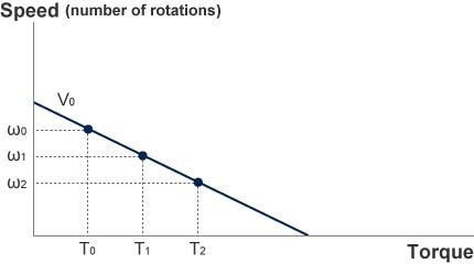
DC motor torque and speed
A look at the relationship between torque and current shows that these are proportional to one another. The ratio between the two is constant for a motor, with the relationship remaining the same regardless of changes in motor speed or drive voltage. This means that measuring the motor current on its own is enough to determine the motor torque.
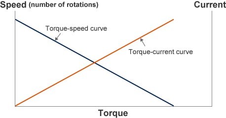
DC motor torque-speed & torque-current curve
So, what happens to the torque-speed curve when the voltage used to drive the DC motor is changed? The graph below shows the torque-speed curves for different voltages. Doubling the drive voltage doubles both the no-load motor speed and the starting torque (torque when motor is locked in position). In other words, increasing the voltage shifts the torque-speed curve upward, parallelly. The torque-speed curve for a DC motor can be adjusted at will, by changing the voltage applied to the motor.
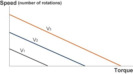
Motor drive voltage and torque curve
Now, given these characteristics, how can you rotate a motor at a required speed at any given load torque?
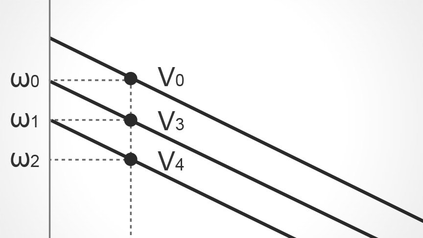
The torque-speed curve of a DC motor translates with changes in drive voltage. This means that the objective above can be achieved by simply adjusting the drive voltage. When looking at the graph below, if the requirement is to rotate at speed ω1 when the load torque is T0, for example, a drive voltage of V4 is too low, resulting in a speed of ω2. A drive voltage of V0 is too high, resulting in a speed of ω0. Driving the motor at the intermediate voltage of V3, however, is just right to achieve the desired speed of ω1.
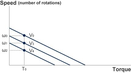
Motor drive voltage and speed
By adjusting the drive voltage in this way, a DC motor can be made to rotate at a desired speed regardless of load torque.
Two ways of adjusting the drive voltage are linear control and PWM control.
Linear control works by placing a variable resistor in series with the motor, and adjusting the resistance to vary the voltage across the motor. While a transistor or other semiconductor device can be used as the serial-connected variable resistor, this approach has poor efficiency due to the large amount of heat generated by the resistance (semiconductor), and therefore it is rarely used these days.
An alternative technique is the PWM control. The voltage applied to the motor can be varied by turning a semiconductor switch (such as a transistor or an FET) on and off at high speed, with the voltage being determined by the on and off pulse widths. The high efficiency of this technique makes it most commonly used nowadays.
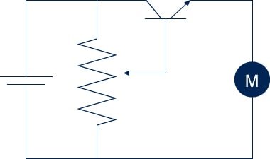
Linear control
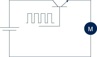
PWM control
Use of these techniques allows the flexible adjustment of DC motor speed. However, additional control is required to keep a motor running at a constant speed. This is because the motor’s load torque varies due to the load itself, as well as other factors such as temperature, humidity, and changes over time. Simply driving the motor with a constant voltage will result in its speed fluctuating with changes in load.
Maintaining a constant speed despite a variable load requires that the drive voltage be continually adjusted in response to these changes in load. The graph below shows an example where the load torque for a motor operating at a speed of ω0 reduces from T1 to T0, in which case reducing the drive voltage to V0 keeps the motor speed at ω0. If the torque instead increases to T2, maintaining a constant motor speed of ω0 requires that the drive voltage increase to V2.
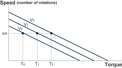
Speed control
The speed is measured by a sensor attached to the motor. The difference between the measured and desired motor speed (speed error) is calculated, and the drive voltage is controlled in such a way that it is increased if the speed is too slow and reduced if the speed is too high. Doing this maintains a constant motor speed. While past practice was to use op amps or other analog circuits to control the drive voltage, the use of microcomputers has become the norm in recent years.
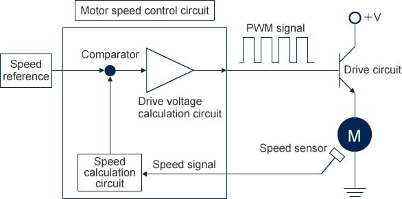
Speed control circuit for brushless DC motor
Speed sensorOutputs a signal indicating the motor speed. Devices used for this purpose include Hall-effect sensors, encoders, and tachogenerators.